第7章 キャリア変調 Digital Transmission via Carrier Modulation 情報を載せたベースバンド信号に正弦波(キャリア)をかけて周波数をシフトする。 Carrier modulation: Shift the frequency of the information bearing signal to the frequency band of channel. 高い周波数を使うことによってアンテナが小型になり,多くの情報が伝送できる。 In the radio communication, antenna size is reduced and much information can be transmitted by use of higher frequency band. ベースバンド信号によって,搬送波の振幅(ASK:振幅シフトキーイング),位相(PSK:位相シフトキーイング),周波数(FSK:周波数シフトキーイング)を変化させる。 Amplitude, phase, or frequency of carrier can be varied by information bearing signal 7.1 キャリア振幅変調 Carrier amplitude modulation 7.1.1 PAM信号の変調 Modulation by PAM ベースバンドのデジタルPAMの信号波 In baseband digital PAM, the waveforms have the form (7.1.1) Amはm番目の波形の振幅,gT(t)は送信信号のスペクトル特性を決定するパルス。 Am is the amplitude of the mth waveform, gT(t) is a pulse whose shape determines the spectral characteristics of the transmitted signal ベースバンド信号のスペクトルが周波数帯域|f|≤Wにあると仮定。 The spectrum of the baseband signal is assumed to be contained in the frequency band |f|≤W Wは図7.1に示す|GT(f)|2の帯域幅。W is bandwidth of |GT(f)|2 信号の振幅は次の離散値をとる Signal amplitude takes the discrete value m=1,2,..,M (7.1.2)
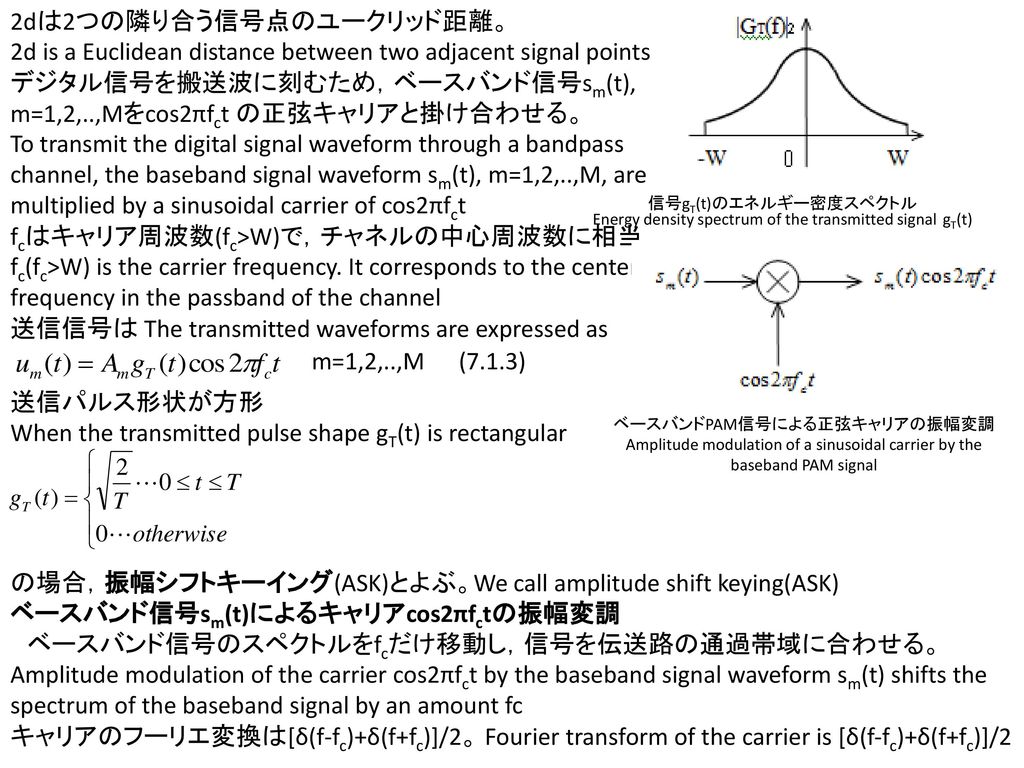
2dは2つの隣り合う信号点のユークリッド距離。 2d is a Euclidean distance between two adjacent signal points デジタル信号を搬送波に刻むため,ベースバンド信号sm(t), m=1,2,..,Mをcos2πfct の正弦キャリアと掛け合わせる。 To transmit the digital signal waveform through a bandpass channel, the baseband signal waveform sm(t), m=1,2,..,M, are multiplied by a sinusoidal carrier of cos2πfct fcはキャリア周波数(fc>W)で,チャネルの中心周波数に相当。 fc(fc>W) is the carrier frequency. It corresponds to the center frequency in the passband of the channel 送信信号は The transmitted waveforms are expressed as 信号gT(t)のエネルギー密度スペクトル Energy density spectrum of the transmitted signal gT(t) m=1,2,..,M (7.1.3) 送信パルス形状が方形 When the transmitted pulse shape gT(t) is rectangular ベースバンドPAM信号による正弦キャリアの振幅変調 Amplitude modulation of a sinusoidal carrier by the baseband PAM signal の場合,振幅シフトキーイング(ASK)とよぶ。We call amplitude shift keying(ASK) ベースバンド信号sm(t)によるキャリアcos2πfctの振幅変調 ベースバンド信号のスペクトルをfcだけ移動し,信号を伝送路の通過帯域に合わせる。 Amplitude modulation of the carrier cos2πfct by the baseband signal waveform sm(t) shifts the spectrum of the baseband signal by an amount fc キャリアのフーリエ変換は[δ(f-fc)+δ(f+fc)]/2。 Fourier transform of the carrier is [δ(f-fc)+δ(f+fc)]/2
時間領域での2つの信号の掛け算は周波数領域でスペクトルの畳み込み。 Multiplication of 2 signals in time domain corresponds to the convolution of their spectra in the frequency domain. 振幅変調されたスペクトルは The spectrum of the amplitude modulated signal is (7.1.4) ベースバンド信号 のスペクトルはキャリア周波数fcだけ移動。 The spectrum of the baseband signal is shifted by carrier frequency fc. 変調された波 The bandpass PAM signal waveform ベースバンドと振幅変調信号のスペクトル Spectra of baseband and amplitude modulated signals (7.1.5) PAM信号の信号点 Signal point constellation for PAM signal 信号波ψ(t)は signal wave form gT(t)は gT(t) is scaled by 倍されねばならない。 to be normalized (7.1.6) m=1,2,..,M (7.1.7) 信号波ψ(t)を単位エネルギーに規格化する The signal waveform ψ(t) is normalized to unit energy (7.1.8) (7.1.9) (7.1.11)
Demodulation of bandpass digital PAM signal sampler To detector PAM変調信号の復調には,相関器やマッチドフィルタが用いられる。ここでは,相関器を使った復調器を考える。 We consider a correlator type demodulator. 受信信号は次のように表される。 The received signal is expressed by Signal pulse generator clock oscillator (7.1.12) PAM変調信号の復調 Demodulation of bandpass digital PAM signal n(t)は雑音で n(t) is a bandpass noise process (7.1.13) nc(t)とns(t)は雑音の直交成分。 nc(t) and ns(t) are the quadrature components of the noise. 式(7.1.6)で与えられるψ(t)と受信信号r(t)の相関を取る。 Cross correlate the received signal with ψ(t) given by (7.1.6) (7.1.14) nは相関器の出力での加法性雑音。雑音成分の中央値は0。分散は N represents the additive noise component at the output. The noise component has a zero mean. The variance is expressed by (7.1.15) Ψ(f)はψ(t)のフーリエ変換で,Sn(f)は加法性雑音の電力スペクトル密度。 Ψ(f) is the Fourier transform of ψ(t). Sn(f)is the power density of the additive noise. ψ(t)のフーリエ変換は The Fourier transform of ψ(t) is (7.1.16)
加法性雑音過程の電力スペクトル密度は Power spectral density of the additive noise is (7.1.17) 式(7.1.16)と(7.1.17)を式(7.1.15)に代入して積分するとΨ(f)は規格化されているので Substitute (7.1.16) and (7.2.17) into (7.1.15) and evaluate the integral 式(7.1.14)から,キャリア変調されたPAMの最適受信機の誤り率はベースバンドPAMと同じ It is apparent (7.1.14), the probability of error of the optimum detector for the carrier modulated PAM signal is identical that of baseband PAM (7.1.18) Eavbはビットあたりの平均エネルギーである。 Eavbis the average energy per bit.
7.2 キャリア位相変調 Carrier Phase Modulation 7.2.1 PSK変調 Phase Shift Keying 送信される情報はキャリアの位相に刻まれる。 The information is impressed on the phase of carrier デジタル情報を送信するために用いられるキャリア位相はθm=2πm/M, m=0,1,..,M-1 The carrier phases used to transmit digital information are θm=2πm/M, m=0,1,..,M-1 M=2の2値位相変調では2つのキャリア位相はθ0=0とθ1=π。 For binary phase modulation(M-2), the two carrier phase are θ0=0とθ1=π M値位相変調ではM=2k。ここでkは送信シンボルあたりのビット数。 For M-ary phase modulation M=2k , k is the number of information bit per transmitted signal. M組のキャリア位相変調信号波の一般的な表現は The general representation of a set of M carrier phase modulated signal waveform is m=0,1,..,M-1 (7.2.1) gT(t)は送信パルス形状で,送信信号のスペクトルを決定。Aは信号の振幅。 gT(t) is the transmitting pulse shape, which determines the spectral characteristics of the transmitted signal. A is the signal amplitude. PSK信号は同じエネルギーを持つ。PSK signal have equal energy (7.2.2) ここでEsは送信シンボルあたりのエネルギー Es denotes the energy per transmitted symbol.
gT(t)が方形パルスの時 When gT(t) is a rectangular pulse (7.2.3) とすれば,シンボル区間0≤t≤Tの送信信号波は The transmitted waveforms in the symbol interval 0≤t≤T is m=0,1,..,M-1 (7.2.4) 式(7.2.4)で与えられる送信信号は一定の包絡線を持ち,キャリアの位相は信号区間の先頭で急激に変化する。図7.6は4相PSK(M=4)。 The transmitted signal given by (7.2.4) have a constant envelope, and the carrier phase change abruptly at the beginning of each signal interval. Four phase (M=4) PSK signal waveform is illustrated in lower right figure. 式(7.2.4)は, Modify (7.2.4) (7.2.5) (7.2.6) (7.2.7) ψ1(t)とψ2(t)は,次に定義される直交基底関数 ψ1(t) and ψ2(t) are orthogonal basis functions defined as
(7.2.8) (7.2.9) パルスgT(t)を適当に規格化することで,2つの基底関数のエネルギーを1に規格化できる。 Appropriately normalizing the pulse shape gT(t), we can normalize the energy of these two basis function to unity. 位相変調信号は各信号区間で送信パルスに応じた振幅を持つ2つの直交キャリアとして表せる。デジタル位相変調信号はsmcとsmsの成分を持つ2次元ベクトルで表わされる。 A phase modulated signal may be viewed as 2 quadrature carriers with amplitudes that depend on the transmitted phase in each signal interval. Digital phase modulated signals are represented geometrically as 2 dimensional vector (7.2.10) 2値位相変調は2値PAMと同じである。 Binary phase modulation is identical to binary PAM. k個の情報ビットのM=2k位相への割り当て: グレーコード:隣り合う信号点が1デジットだけ異なる。送信位相に対し,誤った近接位相を選択すると,グレーコードのkビット系列では1ビット誤りが発生する。 The mapping of k information bit into the M=2k possible phase: PSK信号コンスタレーション Gray encoding: Adjacent phase differ by one binary digit. When noise causes the erroneous selection of an adjacent phase to the transmitted phase, only a single bit errors occur in the k-bit sequence
7.2.2 PSK変調信号の復調とシンボル判定 Phase Demodulation and Detection AWGN伝送路を通過した信号は1シンボル区間で次のように表せる。 The received bandpass signal in a signaling interval from an AWGN channel is expressed as (7.2.11) ここでnc(t)とns(t)は加法性雑音の直交成分。 nc(t)and ns(t) are the 2 quadrature components of the additive noise. 受信信号はψ1(t)とψ2(t)と相関がとられる。 The received signal is correlated with ψ1(t) and ψ2(t) given by (7.2.8) and (7.2.9). 2つの相関器の出力は雑音を含む信号成分を出力する。 The outputs of 2 correlators yield the noise corrupted signal components. (7.2.12) ここでncとnsは (7.2.13) 直交雑音成分nc(t)とns(t)は相関のない中央値0のガウス過程。よってE(nc)=E(ns)=0, E(ncns)=0 nc(t) and ns(t) are the zero mean Gaussian random process that are uncorrelated. As a consequence, E(nc)=E(ns)=0 and E(ncns)=0 ncとnsの分散は The variance of nc and ns (7.2.14) 最適な判定器は,受信信号ベクトルrをMとおりの送信信号ベクトル{sm}の内積をとり,最大の内積に相当するベクトルを選ぶ。
The optimum detector projects the received signal vector r onto each of the M possible transmitted signal vector of {sm}, and selects the vector corresponding to the largest projection. 次の相関メトリクスを考える。Obtain the correlation metrics m=0,1,..,M-1 (7.2.16) 別の判定法:受信信号ベクトルr=(rc,rs)の位相 Another option: Compute the phase of the received signal vector r=(rc,rs) (7.2.17) を計算し,θrに最も近い位相の{sm}から信号を選択する。 Select the signal from set {sm} whose phase is closest to θr 2値位相変調は2値アンチポーダル振幅変調と同じなので,誤り率は Since binary phase modulation is identical to binary PAM, the probability of error is (7.2.18) である。Ebはビットあたりのエネルギーである。Eb is the energy per bit. 4値位相変調は直交キャリア上での2つの2値位相変調とみなせる。よって,ビット誤り率は2値位相変調と同じ。 Four phase modulation is viewed as two binary phase modulation system on quadrature carriers The probability of a bit error is identical to that for binary phase modulation. M>4については閉形式では表せないが,シンボル誤り率は近似的に, For M>4, there is no simple closed form expression for the probability of a symbol error. A good approximation for PM is
(7.2.19) k=log2Mビット/シンボル M値位相変調のビット誤り率は,kビットシンボルを対応する位相にマッピングする方法に依存するため,誘導することが困難。 The equivalent bit error probability for M ary phase modulation is difficult to derive due to the dependence of the mapping of k bit symbol into the corresponding signal phase. グレーコードがマッピングに用いられると,隣接信号点で1ビットしか違わない。雑音によるほとんどの誤りは,真の位相に対し隣の位相を誤って選ぶ。従ってM値位相変調の等価ビット誤り率は次のように近似できる。 When Gray code is used in mapping, 2 k-bit symbols corresponding to adjacent signal phase differ in only single bit. Most probable errors due to noise results in the erroneous selection of an adjacent phase to the true phase. The equivalent bit error probability for M-ary phase modulation is well approximated as (7.2.20) 例7-3 PSKシミュレーション PSK simulation 式(7.2.16)で与えられる相関メトリクスを計算する判定器をモデル化し,4値PSK通信システムのモンテカルロシミュレーションを実行せよ。シミュレーションモデルを図7.9に示す。
判定器入力となる式(7.2.12)のベクトルrを次のように発生する. Perform Monte Carlo simulation of an M=4 PSK communication system that models the detector as the one that computes the correlation metrics given in (7.2.16). symbol error counter Gaussian RNG 4 PSK mapping compare Gaussian RNG detector Uniform random number generator Bit error counter 解 Solution 判定器入力となる式(7.2.12)のベクトルrを次のように発生する. Generate random vector r given by (7.2.12), which is input to the detector 図7.7の4信号点にマッピングされた2ビットシンボル系列を発生 Generate a sequence of quaternary (2bit) synbols that are mapped into the corresponding 4 phase signal points. (0,1)の範囲で一様乱数を発生させ,この範囲を4つの等間隔(0,0.25), (0.25,0.5), (0.5,0.75), (0.75,1)に分割。各区間が情報ビット00, 01, 11, 10に対応。 Generate a uniform random number in the range (0,1). This range is subdivided into 4 equal intervals, (0,0.25), (0.25,0.5), (0.5,0.75), (0.75,1). The subintervals correspond to pairs of information bit 00, 01, 11, and 01. Also, these are used to select the signal phase vector sm 加法性雑音成分nc, nsは統計的に独立な中央値0,分散σ2をもつガウス過程.簡単のため分散をσ2=1に規格化し,信号のエネルギーEsを調整して受信信号のSNRを制御する。
The additive white noise nc and ns are statiscally independent zero mean Gaussian random variables with variance σ2. For convenience, normalize the variance to σ2=1, control the SNR in the received signal by scaling the signal energy parameter Es. 判定器は受信信号ベクトルr=sm+nを観測し,4つの取りえる信号ベクトルsm上へのrの投影(ドット積)を計算し,最も大きな投影に相当する信号点を選ぶ.判定出力は,送信シンボルと比較され,シンボル誤りとビット誤りが計数される. The detector observes the received signal vector r=sm+n and compute the projection of r onto the four possible signal vector sm Decision is based on selecting the signal corresponding in the largest projection. The output decisions are compared with the transmitted symbol and symbol errors and bit errors are counted. 図7.12はN=10000シンボル送信のモンテカルロシミュレーションの結果で,Eb/N0と誤り率の関係.ここでEb=Es/2はビットエネルギー.図7.12ではPb=PM/2とし,式(7.2.19)から導かれた理論的なビット誤り率も示している. Fig. 7.12 illustrates the results of the Monte Carlo simulation for the transmission of 10000 symbols at different value of SNR(Eb/N0). Eb=Es/2 is the bit energy. Also, the bit error rate which is defined as Pb=PM/2 and the corresponding theoretical error probability is also shown. (7.2.19)